
Logic circuits are designed to perform specific functions that enable computers to run properly.
Every logic circuit is made up of several logic gates, which take binary inputs and produce binary outputs. The relationship between these inputs and outputs is based on a certain type of logic, which is represented by boolean algebra.
The most common Boolean operators are AND, OR and NOT.
A NOT gate has only one input. The output of the circuit will be the opposite of the input. If 0 is input, then the output is 1. If 1 is input, then 0 is output.
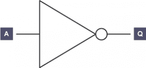
Truth tables provide all the possible results of a Boolean algebra statement. They are used to check the output from a logic gate or logic circuit. In the example above, if A is the input and Q is the output, the truth table looks like this:
| A | Q |
|---|---|
| 1 | 0 |
| 0 | 1 |
The NOT gate is the only logic gate with one input; the other five gates have two inputs.
The NOT Boolean expression is written as Q = NOT A.
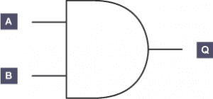
An AND gate can be used on a gate with two inputs. AND tells us that both inputs have to be 1 in order for the output to be 1.
AND gate truth table:
| A | B | Q |
|---|---|---|
| 0 | 0 | 0 |
| 0 | 1 | 0 |
| 1 | 0 | 0 |
| 1 | 1 | 1 |
The AND Boolean expression is written as Q = A AND B.
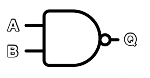
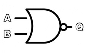
The NAND gate behaves in the opposite fashion to the AND gate. You can think of it as an AND gate followed immediately by a NOT gate. Its output is 0 when the two inputs are 1, and for all other cases, its output is 1. The name NAND comes from joining NOT and AND. The symbol for NAND is the same as that for AND except for the addition of a small circle on the right side.
![]()
| A | B | Q |
|---|---|---|
| 0 | 0 | 1 |
| 0 | 1 | 1 |
| 1 | 0 | 1 |
| 1 | 1 | 0 |
The NAND Boolean expression is written as Q = A NAND B
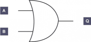
The OR gate has two inputs. One or both inputs must be 1 to output 1, otherwise it outputs 0.
OR gate truth table:
| A | B | Q |
|---|---|---|
| 0 | 0 | 0 |
| 0 | 1 | 1 |
| 1 | 0 | 1 |
| 1 | 1 | 1 |
The Boolean expression is written as Q = A OR B.
A NOR gate can be thought of as an OR also followed by a NOT. The output, Q, is 1 if neither input A nor B is 1.
NOR gate truth table:
| A | B | Q |
|---|---|---|
| 0 | 0 | 1 |
| 0 | 1 | 0 |
| 1 | 0 | 0 |
| 1 | 1 | 0 |
The Boolean expression is written as Q = A NOR B
The exclusive OR (XOR) gate works the same as an OR gate, but will output 1 only if one or the other (not both) inputs are 1.
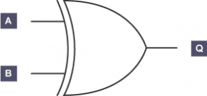
XOR gate truth table:
| A | B | Q |
|---|---|---|
| 0 | 0 | 0 |
| 0 | 1 | 1 |
| 1 | 0 | 1 |
| 1 | 1 | 0 |
The Boolean expression is written as Q = A XOR B.
Complex logic circuits are made up of several logic gates that are built up into chains of logical decisions. The diagram below shows a complex logic circuit combining three simple gates. The first two logic gates are OR gates, the third logic gate is an AND gate.
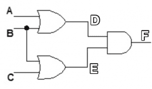
Altogether there are three inputs (A, B and C), which lead to eight possible outcomes. To solve the truth below, first find D, then E and finally F. Complete a whole columnn before moving on to the next column. D depends on A or B, E depends on B or C, and F depends on D and E.
This logic gate truth table is written as:
| A | B | C | D = A OR B | E = B OR C | F = D AND E |
|---|---|---|---|---|---|
| 0 | 0 | 0 | 0 | 0 | 0 |
| 0 | 0 | 1 | 0 | 1 | 0 |
| 0 | 1 | 0 | 1 | 1 | 1 |
| 0 | 1 | 1 | 1 | 1 | 1 |
| 1 | 0 | 0 | 1 | 0 | 0 |
| 1 | 0 | 1 | 1 | 1 | 1 |
| 1 | 1 | 0 | 1 | 1 | 1 |
| 1 | 1 | 1 | 1 | 1 | 1 |